

THE TIER-1 ENGINEER
ENGINEERING AND MANUFACTURING
SIMPLIFIED

The process excels at producing large, lightweight, thin-walled parts with good cosmetic quality on one side and relatively low tooling cost. Common applications include packaging trays, blister packs, appliance liners, refrigerator interiors, automotive interior panels, medical trays, and point-of-purchase displays. These parts are typically produced in the thousands to hundreds of thousands, where injection molding tooling cost or lead time cannot be justified.
Thermoforming equipment generally consists of a sheet clamping system, a heating station, a forming station using vacuum and or pressure, a cooling stage, and a trimming operation. Tooling is typically aluminum or composite rather than hardened steel, which keeps cost and lead time low but limits precision and durability.
Thermoforming performs best when it is selected intentionally and designed honestly. Most production issues trace back to designs that assume injection-molding behavior from a process that fundamentally does not behave that way.
ENGINEERING
DRAWINGS
Even in a world dominated by 3D CAD models, engineering drawings remain one of the most important tools in product development and manufacturing. A CAD model may define the shape of a part, but the engineering drawing is what communicates exactly how that part must be manufactured, inspected, and assembled. Dimensions, tolerances, notes, and symbols turn a digital model into a precise set of instructions that machinists, fabricators, and suppliers can follow.
Engineering drawings act as the shared language between designers and the people responsible for producing the parts. A well-constructed drawing removes ambiguity by clearly defining the size, location, and relationship of every critical feature. When done correctly, it allows teams across different companies, shops, and even countries to manufacture the same component consistently and reliably.

This page introduces the absolute basic elements that make up a professional engineering drawing. This is not intended to be a training resource for every niche annotation or an outline of drawing standards. You’ll learn how multiple views are used to describe three-dimensional geometry, how dimensions and tolerances define allowable variation, how title blocks and revision tables control documentation, and how notes and symbols communicate manufacturing requirements. These fundamentals form the backbone of technical communication in mechanical design and are used every day across industries ranging from consumer products to aerospace manufacturing.
The process excels at producing large, lightweight, thin-walled parts with good cosmetic quality on one side and relatively low tooling cost. Common applications include packaging trays, blister packs, appliance liners, refrigerator interiors, automotive interior panels, medical trays, and point-of-purchase displays. These parts are typically produced in the thousands to hundreds of thousands, where injection molding tooling cost or lead time cannot be justified.
Thermoforming equipment generally consists of a sheet clamping system, a heating station, a forming station using vacuum and or pressure, a cooling stage, and a trimming operation. Tooling is typically aluminum or composite rather than hardened steel, which keeps cost and lead time low but limits precision and durability.
Thermoforming performs best when it is selected intentionally and designed honestly. Most production issues trace back to designs that assume injection-molding behavior from a process that fundamentally does not behave that way.
ORTHOGRAPHIC VIEWS
One of the biggest challenges in engineering communication is representing a three-dimensional object on a two-dimensional drawing. While perspective images or 3D renderings can show what a part looks like, they often distort size relationships and make it difficult to apply precise measurements. Orthographic views solve this problem by breaking a part into multiple flat views that show the geometry clearly and without distortion.
Instead of relying on a single perspective image, engineering drawings typically represent a part using several carefully aligned views. Each view shows the object from a specific direction, allowing dimensions, locations, and relationships between features to be defined precisely. By combining multiple views, engineers can describe the complete geometry of a part while keeping the drawing readable and unambiguous.
This system allows machinists, inspectors, and manufacturing teams to interpret the shape of a component accurately without needing to see the original CAD model. When used correctly, orthographic views provide a clear and standardized method for communicating complex three-dimensional geometry on a two-dimensional drawing.

PRIMARY ORTHOGRAPHIC VIEWS


The top view shows the part as it would appear when looking straight down from above. It helps define the width and placement of features that may not be fully visible in the front view.
TOP VIEW
The top view aligns vertically with the front view


FRONT VIEW
The front view is usually the most informative view of the part and often serves as the reference for the rest of the drawing. It typically shows the largest amount of geometry or the most important functional features.
RIGHT VIEW
The right-side view shows the part when viewed from the right side. This view often reveals depth relationships and additional geometry that cannot be clearly seen in the other views.
The right-side view aligns horizontally with the front view
PROJECTION STYLES
THIRD ANGLE PROJECTION


Third-angle projection is the standard used in the United States and most North American engineering drawings.
In third-angle projection, the views are placed on the drawing in the same direction that the part is viewed.
FIRST ANGLE PROJECTION


First-angle projection is commonly used in Europe and many international engineering standards.
In this system, the views are projected through the part and placed on the opposite side of the viewing direction.
The process excels at producing large, lightweight, thin-walled parts with good cosmetic quality on one side and relatively low tooling cost. Common applications include packaging trays, blister packs, appliance liners, refrigerator interiors, automotive interior panels, medical trays, and point-of-purchase displays. These parts are typically produced in the thousands to hundreds of thousands, where injection molding tooling cost or lead time cannot be justified.
Thermoforming equipment generally consists of a sheet clamping system, a heating station, a forming station using vacuum and or pressure, a cooling stage, and a trimming operation. Tooling is typically aluminum or composite rather than hardened steel, which keeps cost and lead time low but limits precision and durability.
Thermoforming performs best when it is selected intentionally and designed honestly. Most production issues trace back to designs that assume injection-molding behavior from a process that fundamentally does not behave that way.
SECTION & DETAIL VIEWS
Even with multiple orthographic views, some features of a part can still be difficult to interpret. Internal cavities, hidden holes, and complex geometry may not be clearly visible when looking only at the exterior surfaces of a component. To solve this problem, engineering drawings use section views and detail views to reveal information that would otherwise be hidden or difficult to interpret.
Section views allow the viewer to see inside a part by representing the object as if it were sliced along a specific plane. Detail views, on the other hand, zoom in on small areas of the drawing to show features that would be too small or crowded to interpret clearly at the normal drawing scale. Together, these techniques make complex parts easier to understand and help ensure that manufacturing and inspection teams interpret the design correctly.
SECTION VIEWS
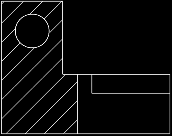
A section view represents a part as if it has been cut along an imaginary plane, exposing the internal geometry of the component.

Section views are commonly used to show internal features such as cavities, internal ribs, counterbores, threaded holes, and other geometry that cannot be seen from the outside. Instead of relying on hidden lines, which can clutter a drawing, a section view removes the front portion of the part and displays the interior features clearly.
When a section view is created, the surfaces where the imaginary cut occurs are typically filled with a pattern of thin diagonal lines called section hatching. These lines indicate that the material has been cut through by the section plane.
CUTTING PLANE LINES
Section views begin with a cutting plane line, which shows where the imaginary slice through the part occurs.
The cutting plane line is typically drawn as a thick line with arrows indicating the direction of the viewing angle. Labels such as A–A or B–B are used to identify the section view that corresponds to the cut location.

A
A
SECTION TYPES

FULL SECTION

A full section cuts entirely through the part along a single plane. This is the most common type of section view and is used when the internal features of the entire component need to be shown clearly.
HALF SECTION

Half sections are commonly used for symmetrical parts. One half of the view shows the exterior geometry, while the other half shows the interior cross-section.
OFFSET SECTION


Offset sections are commonly used when certain features must be shown within one section view, but they are not in the plane of the section line. An offset line cuts the part.
DETAIL VIEWS
Detail views enlarge a small portion of a drawing so that fine features can be shown clearly.

Some features on a part may be too small to dimension or interpret at the scale of the main drawing. Detail views isolate a specific region of the drawing and display it at a larger scale so that dimensions, notes, and geometry can be shown more clearly.
Detail views are typically identified by a circular callout on the main drawing and labeled with a letter such as Detail A. The enlarged view then appears elsewhere on the drawing sheet with a scale that allows the feature to be clearly defined.
Detail views are commonly used for features such as small fillets, threads, chamfers, grooves, or other localized geometry that would otherwise be difficult to communicate.

The process excels at producing large, lightweight, thin-walled parts with good cosmetic quality on one side and relatively low tooling cost. Common applications include packaging trays, blister packs, appliance liners, refrigerator interiors, automotive interior panels, medical trays, and point-of-purchase displays. These parts are typically produced in the thousands to hundreds of thousands, where injection molding tooling cost or lead time cannot be justified.
Thermoforming equipment generally consists of a sheet clamping system, a heating station, a forming station using vacuum and or pressure, a cooling stage, and a trimming operation. Tooling is typically aluminum or composite rather than hardened steel, which keeps cost and lead time low but limits precision and durability.
Thermoforming performs best when it is selected intentionally and designed honestly. Most production issues trace back to designs that assume injection-molding behavior from a process that fundamentally does not behave that way.
DIMENSIONS
While orthographic and section views show the shape of a part, dimensions define the exact size and location of its features. Without dimensions, a drawing is simply a picture of an object. Dimensions turn that picture into a precise set of instructions that can be used to manufacture and inspect the component.
Dimensions communicate measurements such as lengths, diameters, angles, and distances between features. These values allow machinists, fabricators, and inspectors to produce the part accurately and verify that the finished component meets the design requirements.
Good dimensioning removes ambiguity. A well-dimensioned drawing clearly defines every important feature of a part while avoiding unnecessary or conflicting measurements. In the manufacturing world, the dimensioning scheme and clarity of a drawing directly relate to how many fights you'll have with the shop floor or supplier.
TYPES OF DIMENSIONS
LINEAR DIMENSIONS
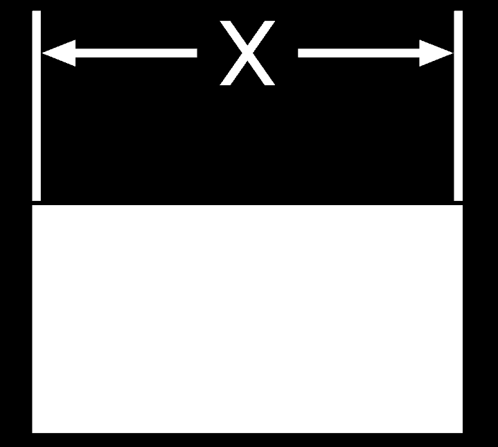
Linear dimensions define straight-line distances between features. These are commonly used to specify lengths, widths, heights, and the spacing between holes or edges.
DIAMETER DIMENSIONS
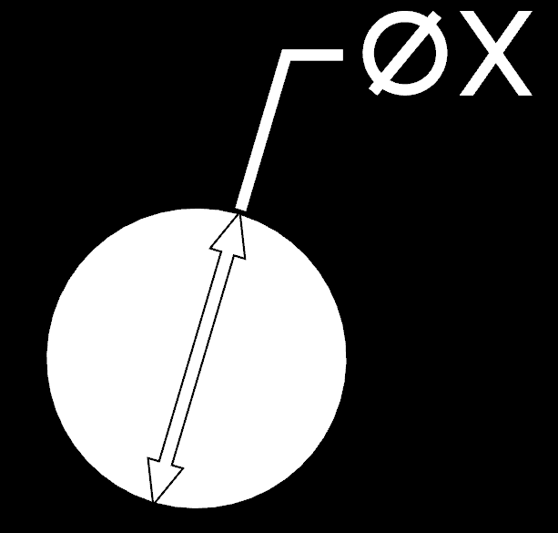
Circular features such as holes and cylinders are often defined using diameter dimensions. These are typically indicated by the diameter symbol (⌀) placed before the dimension value.
RADIUS DIMENSIONS

Arcs and rounded edges are defined using radius dimensions. The radius symbol (R) indicates the distance from the center of the arc to its edge.
ANGULAR DIMENSIONS

Angular dimensions define the angle between two intersecting lines or surfaces. These are often used for tapered features, chamfers, or angled surfaces.
DIMENSION PLACEMENT
Dimensions are placed on drawings in a way that keeps the drawing readable and easy to interpret. Whenever possible, dimensions are positioned outside the part geometry to avoid clutter and overlapping lines. Keeping dimensions organized and readable is essential for ensuring that the drawing communicates the design clearly.

DIMENSIONING STRATEGIES
There are several ways to apply dimensions to a drawing depending on the design intent and the features being defined. Designers typically choose dimensioning methods that clearly define the part while minimizing ambiguity and potential manufacturing variation.
BASELINE DIMENSIONING

In baseline dimensioning, multiple features are measured from a common reference edge or surface. This method helps reduce the stack-up of dimensional variation across a part.
CHAIN DIMENSIONING
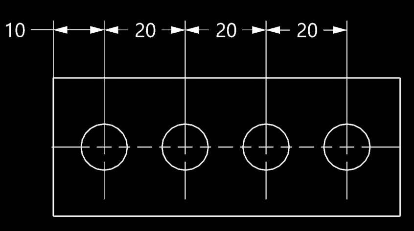
In chain dimensioning, multiple features are measured relative to each other. This method tends to introduce a stack-up of tolerance along the feature pathway.

GEOMETRIC DIMENSIONING
Geometric dimensioning defines the shape, orientation, and position of features using specialized symbols rather than simple linear measurements. Instead of only specifying size, geometric tolerances control how features must relate to each other in three-dimensional space. For example, a geometric tolerance might specify how flat a surface must be, how perpendicular a hole must be relative to another surface, or how accurately a feature must be positioned within a part.
TOLERANCES
Dimensions define the intended size and location of features on a part, but in the real world no component can be produced with perfect precision. Every manufacturing process introduces small variations caused by machine capability, material behavior, tool wear, and measurement uncertainty. Because of this, engineering drawings specify not only the nominal (exact, as-designed) size of a feature but also the allowable range of variation for that feature
This acceptable variation is called a tolerance. Tolerances ensure that parts can still function correctly even when small manufacturing variations occur. For example, a hole and a shaft that must fit together may each be allowed to vary slightly in size, but their tolerances must be defined so the parts will still assemble properly when each component is at it's worst-case tolerance state.
This indicates that the feature is intended to be 25.00 units in size but may vary by 0.1 units equally in either direction. In this case, 25.10 is the maximum that this feature is allowed to be, and 24.90 is the minimum. These max/min determinations are driven from: the needs of the design (specifically in a mating or assembly scenario), manufacturing process tolerances, and cost (tighter tolerances=more expensive manufacturing).
Defining tolerances correctly is critical because overly tight tolerances can make parts expensive or difficult to manufacture, while tolerances that are too loose can lead to poor fit, reduced performance, or assembly problems.
More advanced tolerance systems, such as Geometric Dimensioning and Tolerancing (GD&T), provide additional ways to control the shape, orientation, and position of features. These systems allow engineers to communicate functional requirements more precisely and are commonly used in high-precision manufacturing. A deeper look at tolerances and fits is covered in the Tolerancing and Fitment section of this site.

The process excels at producing large, lightweight, thin-walled parts with good cosmetic quality on one side and relatively low tooling cost. Common applications include packaging trays, blister packs, appliance liners, refrigerator interiors, automotive interior panels, medical trays, and point-of-purchase displays. These parts are typically produced in the thousands to hundreds of thousands, where injection molding tooling cost or lead time cannot be justified.
Thermoforming equipment generally consists of a sheet clamping system, a heating station, a forming station using vacuum and or pressure, a cooling stage, and a trimming operation. Tooling is typically aluminum or composite rather than hardened steel, which keeps cost and lead time low but limits precision and durability.
Thermoforming performs best when it is selected intentionally and designed honestly. Most production issues trace back to designs that assume injection-molding behavior from a process that fundamentally does not behave that way.
TITLE BLOCKS
Every engineering drawing includes a title block that identifies the part and provides key information about the document. While the drawing views and dimensions describe the geometry of the component, the title block defines the administrative and technical details needed to manage the design within an engineering workflow.
In production environments, drawings are controlled documents. They must clearly identify what part is being described, what revision of the design is being used, and who created or approved the drawing. The title block collects this information in a consistent location so that engineers, manufacturers, and inspectors can quickly confirm they are working from the correct version of the design.
Although the exact layout of a title block can vary between companies, most drawings include a common set of fields that communicate the essential information about the part and the document itself.

PART NUMBER
A unique identifier used to track the component within an engineering system. This number allows the drawing to be referenced in bills of materials, manufacturing documentation, and revision control systems.
PART NAME / DESCRIPTION
The name of the component shown in the drawing. This provides a quick description of what the part is and how it fits into the product or assembly.
MATERIAL SPECIFICATION
Many drawings specify the material used to manufacture the component. This may include a standard material designation or a specific alloy or plastic grade.
UNITS
The title block indicates the measurement units used in the drawing, such as millimeters or inches. This prevents confusion when drawings are shared between teams or companies that may use different unit systems.
AUTHOR / APPROVALS
Many engineering drawings include fields identifying the engineer who created the drawing and the person responsible for reviewing or approving it. This helps maintain accountability and traceability.
REVISION LEVEL
The revision identifies the current version of the design. When changes are made to a part, the revision is updated so that manufacturing and inspection teams know which version of the drawing is valid.
SCALE
The scale shows how the drawing relates to the actual size of the part. Some drawings are shown at full scale, while others may be enlarged or reduced to fit the drawing sheet.
COMPANY INFORMATION
Virtually all engineering drawings have the owning company information included in the title block. This serves as traceability, responsibility, and brand awareness.
REVISION BLOCK

Most engineering drawings include a revision table located near the title block. This table records the history of changes made to the drawing and provides a clear record of how the design has evolved over time. In production environments, maintaining an accurate revision history is critical because even small design changes can affect manufacturing processes, assembly fit, tooling, or inspection requirements.
When a drawing is modified, the revision identifier is updated and a short description of the change is added to the revision table. This allows anyone reading the drawing to quickly determine whether the document has been updated and what aspects of the design were changed. Without this system, teams risk producing parts from outdated information, which can lead to scrap, rework, or assembly issues.
Revision tables typically include several key pieces of information. The revision identifier indicates the version of the drawing, often using letters or numbers to track successive updates. A description of the change briefly explains what was modified in that revision, such as a dimension update, a material change, or the addition of a feature. The table also commonly records the date of the revision and the engineer or approver responsible for the change, providing traceability within the design process.
In larger organizations, revision control is closely tied to engineering documentation systems and change management procedures. Updates to a drawing may be linked to formal change records such as Engineering Change Orders (ECOs) or Engineering Change Notices (ECNs). These systems ensure that design changes are reviewed, approved, and communicated properly before new parts are manufactured.
For anyone working with engineering drawings, checking the revision level is an essential first step. Before interpreting dimensions or manufacturing a part, engineers and machinists confirm that they are working from the latest approved revision of the drawing.
The process excels at producing large, lightweight, thin-walled parts with good cosmetic quality on one side and relatively low tooling cost. Common applications include packaging trays, blister packs, appliance liners, refrigerator interiors, automotive interior panels, medical trays, and point-of-purchase displays. These parts are typically produced in the thousands to hundreds of thousands, where injection molding tooling cost or lead time cannot be justified.
Thermoforming equipment generally consists of a sheet clamping system, a heating station, a forming station using vacuum and or pressure, a cooling stage, and a trimming operation. Tooling is typically aluminum or composite rather than hardened steel, which keeps cost and lead time low but limits precision and durability.
Thermoforming performs best when it is selected intentionally and designed honestly. Most production issues trace back to designs that assume injection-molding behavior from a process that fundamentally does not behave that way.
GENERAL NOTES
In addition to views, dimensions, and tolerances, most engineering drawings include a set of general notes that communicate requirements applying to the entire part. These notes provide important manufacturing instructions that would be difficult or unnecessary to repeat throughout the drawing.
General notes often specify things such as finishing requirements, material conditions, inspection standards, or basic manufacturing expectations. By placing this information in a dedicated section of the drawing, engineers ensure that everyone involved in producing or inspecting the part understands the overall requirements without cluttering the drawing with repeated instructions.
General notes are typically located near the title block or along the edge of the drawing sheet so they are easy to find and reference during manufacturing or inspection.
COMMON NOTATIONS
General notes are used to communicate instructions that apply to the entire component rather than a single feature. These instructions help ensure that parts are manufactured consistently and that important details are not overlooked.
MATERIAL AND SECONDARY OPS
Notes may reinforce the material specification or describe required heat treatment, coating, or finishing processes.
GENERAL TOLERANCES
Some drawings include default dimensional tolerances that apply when a specific tolerance is not given.
SURFACE FINISH REQUIREMENTS
General notes may specify surface finish expectations for the entire part or define default requirements unless otherwise noted.
EDGE CONDITIONS
Many drawings include instructions to break or remove sharp edges and burrs created during machining or fabrication.
MANUFACTURING INSTRUCTIONS
General notes sometimes include specific instructions relevant to fabrication or machining of the part.
GENERAL REQUIREMENTS
General notes are often used as a "catch-all" to communicate instructions or requirements specific to the part or assembly.
1.
2.
3.
4.
5.
6.
7.
8.
9.
MATERIAL: 6061-T6 ALUMINUM UNLESS OTHERWISE SPECIFIED.
SECONDARY OPERATIONS SUCH AS HEAT TREATMENT, COATING, OR PLATING SHALL BE PER DRAWING REQUIREMENTS.
UNLESS OTHERWISE SPECIFIED, GENERAL DIMENSIONAL TOLERANCES APPLY:
.X ±0.1
.XX ±0.03
.XXX ±0.010
ANGLES ±1°
SURFACE FINISH: 125 µin Ra MAX UNLESS OTHERWISE SPECIFIED.
BREAK ALL SHARP EDGES: 0.010–0.020.
REMOVE ALL BURRS AND SHARP PROJECTIONS.
DIMENSIONS APPLY AFTER ALL FINISHING OPERATIONS UNLESS OTHERWISE SPECIFIED.
DO NOT SCALE DRAWING.
MANUFACTURE PART PER CURRENT REVISION OF THIS DRAWING.
EXAMPLE
GENERAL NOTES
THE IMPORTANCE OF GENERAL NOTES
General notes help keep drawings clear and readable while still communicating important requirements. Without them, many instructions would need to be repeated throughout the drawing, creating clutter and increasing the risk that critical information could be missed.
In production environments, machinists and inspectors often review the general notes before interpreting the rest of the drawing. These notes establish the baseline expectations for how the part should be manufactured and finished. For this reason, engineers should write general notes carefully and ensure they clearly communicate the intended requirements without ambiguity.
The process excels at producing large, lightweight, thin-walled parts with good cosmetic quality on one side and relatively low tooling cost. Common applications include packaging trays, blister packs, appliance liners, refrigerator interiors, automotive interior panels, medical trays, and point-of-purchase displays. These parts are typically produced in the thousands to hundreds of thousands, where injection molding tooling cost or lead time cannot be justified.
Thermoforming equipment generally consists of a sheet clamping system, a heating station, a forming station using vacuum and or pressure, a cooling stage, and a trimming operation. Tooling is typically aluminum or composite rather than hardened steel, which keeps cost and lead time low but limits precision and durability.
Thermoforming performs best when it is selected intentionally and designed honestly. Most production issues trace back to designs that assume injection-molding behavior from a process that fundamentally does not behave that way.
COMMON SYMBOLS
Engineering drawings use a set of standardized symbols to communicate information efficiently. These symbols allow engineers to describe common features and requirements without writing lengthy notes or explanations on the drawing.
Many of these symbols appear directly next to dimensions or feature callouts and indicate things such as hole types, surface conditions, or geometric requirements. Because these symbols follow widely accepted drafting standards, machinists and engineers across different companies and industries can interpret drawings consistently.
Learning to recognize these symbols is an important step toward reading engineering drawings with confidence.
DIAMETER

Indicates the dimension applies to a circular feature such as a hole or shaft, representing the full width across the feature.
RADIUS

Specifies the radius of an arc or rounded feature, commonly used for fillets, rounds, and curved transitions between surfaces.
COUNTERSINK

Indicates a conical feature at the top of a hole, commonly used to accommodate flat head screws or chamfered edges.
COUNTERBORE

Specifies a cylindrical recessed feature above a hole, typically used to allow bolt heads or fasteners to sit flush.
DEPTH

Indicates the depth of a feature such as a hole or pocket, measured from the surface down to the bottom.
ANGLE

Specifies the angle between two lines or surfaces, typically defined in degrees to control orientation and ensure proper feature alignment.
SPHERICAL DIAMETER

S
Indicates the diameter of a spherical feature, such as a ball or dome, representing the full size across the spherical geometry.
CENTERLINE

Represents the axis or center of a feature, used to define symmetry, alignment, and reference locations for circular or repeating geometry.
SURFACE FINISH

Specifies the required surface roughness of a feature, ensuring proper function, wear performance, sealing capability, or interaction with mating components.
WELD

Indicates the presence and type of a weld, defining joint geometry, weld size, and placement for proper fabrication and structural performance.